Transforms & Coordinate Frames
Rerun comes with built-in support for modeling spatial relationships between entities. This page details how the different archetypes involved interact with each other and explains how transforms are set up in Rerun.
Transform hierarchies with entity paths transform-hierarchies-with-entity-paths
The Transform3D archetype allows you to specify how one coordinate system relates to another through translation, rotation, and scaling.
The simplest way to use transforms is through entity path hierarchies, where each transform describes the relationship between an entity and its parent path. Note that by default, all entities are connected via identity transforms.
"""Logs a simple transform hierarchy."""

import rerun as rr

rr.init("rerun_example_transform3d_hierarchy_simple", spawn=True)

# Log entities at their hierarchy positions
rr.log("sun", rr.Ellipsoids3D(centers=[0, 0, 0], half_sizes=[1, 1, 1], colors=[255, 200, 10]))
rr.log("sun/planet", rr.Ellipsoids3D(centers=[0, 0, 0], half_sizes=[0.4, 0.4, 0.4], colors=[40, 80, 200]))
rr.log("sun/planet/moon", rr.Ellipsoids3D(centers=[0, 0, 0], half_sizes=[0.15, 0.15, 0.15], colors=[180, 180, 180]))

# Define transforms - each describes the relationship to its parent
rr.log("sun/planet", rr.Transform3D(translation=[6.0, 0.0, 0.0]))  # Planet 6 units from sun
rr.log("sun/planet/moon", rr.Transform3D(translation=[3.0, 0.0, 0.0]))  # Moon 3 units from planet
In this hierarchy:
- The
sunentity exists at the origin of its own coordinate system - The
sun/planettransform places the planet 6 units from the sun, along the x-axis - The
sun/planet/moontransform places the moon 3 units along x away from the planet
This creates a transform hierarchy where transforms propagate down the entity tree. The moon's final position in the sun's coordinate system is 9 units away (6 + 3), because the transforms are applied sequentially.
Named transform frames named-transform-frames
While entity path hierarchies work well for many cases, sometimes you need more flexibility in organizing your transforms. In particular for anyone familiar with ROS we recommend using named transform frames as it allows you to model your data much closer to how it would be defined when using ROS' tf2 library.
By explicitly specifying transform frames, you can decouple spatial relationships from the entity hierarchy.
Instead of relying on entity path relationships, each entity is first associated with a named transform frame using
the CoordinateFrame archetype.
The relationship between transform frames is then determined by logging Transform3D
with child_frame and parent_frame parameters to define the geometric relationship between two transform frames.
TODO: make tested cross language snippet
import rerun as rr
import numpy as np

rr.init("named_frames_example", spawn=True)
rr.log("/", rr.ViewCoordinates.RIGHT_HAND_Z_UP, static=True)

# Define entities with named coordinate frames
rr.log("sun", rr.Ellipsoids3D(centers=[0, 0, 0], half_sizes=[1, 1, 1], colors=[255, 200, 10]),
       rr.CoordinateFrame("sun_frame"))
rr.log("planet", rr.Ellipsoids3D(centers=[0, 0, 0], half_sizes=[0.4, 0.4, 0.4], colors=[40, 80, 200]),
       rr.CoordinateFrame("planet_frame"))
rr.log("moon", rr.Ellipsoids3D(centers=[0, 0, 0], half_sizes=[0.15, 0.15, 0.15], colors=[180, 180, 180]),
       rr.CoordinateFrame("moon_frame"))

# Connect the viewer to the sun's coordinate frame
rr.log("/", rr.CoordinateFrame("sun_frame"))

# Define frame relationships
rr.log("planet_transform", rr.Transform3D(
    translation=[6.0, 0.0, 0.0],
    child_frame="planet_frame",
    parent_frame="sun_frame"
))
rr.log("moon_transform", rr.Transform3D(
    translation=[3.0, 0.0, 0.0],
    child_frame="moon_frame",
    parent_frame="planet_frame"
))
Note that unlike in ROS, you can log your transform relationship on any entity. However, currently once a relation between two frames has been logged to an entity, this relation may no longer be logged on any other entity.
Named transform frames have several advantages over entity path based hierarchies:
- topology may change over time
- which entity is associated with which frame may change over time (it can also be overridden via blueprint)
- several entities may be associated with the same frame
- frees up entity paths for semantic rather than geometric organization
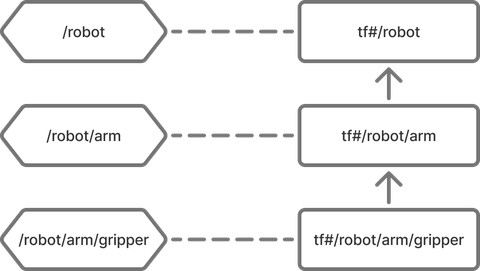
Entity hierarchy based transforms under the hood - implicit transform frames entity-hierarchy-based-transforms-under-the-hood--implicit-transform-frames
Under the hood, Rerun's entity path hierarchies actually use the same transform frame system as named frames.
For each entity path, an associated transform frame with the prefix tf# is automatically created:
for example, an entity /world/robot gets frame tf#/world/robot.
Path based hierarchies are then established by defaults the Viewer uses (also referred to as fallbacks):
Given an entity /world/robot:
- if no
CoordinateFrame::frameis specified, it automatically defaults totf#/world/robot - if no
Transform3D::child_frameis specified, it automatically defaults totf#/world/robot - if no
Transform3D::parent_frameis specified, it automatically defaults to the parent's implicit frame,tf#/world
The only special properties these implicit frames have over their named counterparts is that they have implicit identity relationships.
Example example
Given these entities: TODO: xlanguage please
rr.log("robot", rr.Transform3D(translation=[1, 0, 0]))
rr.log("robot/arm", rr.Transform3D(translation=[0, 1, 0]))
rr.log("robot/arm/gripper", rr.Points3D([0, 0, 0]))
Rerun will interpret this as-if it was logged with the named transform frames like so:
TODO: xlanguage please
rr.log("robot",
    rr.CoordinateFrame("tf#/robot"),
    rr.Transform3D(
        translation=[1, 0, 0],
        child_frame="tf#/robot",
        parent_frame="tf#/"
    )
)
rr.log("robot/arm",
    rr.CoordinateFrame("tf#/robot/arm"),
    rr.Transform3D(
        translation=[0, 1, 0],
        child_frame="tf#/robot/arm",
        parent_frame="tf#/robot"
    )
)
rr.log("robot/arm/gripper",
    rr.CoordinateFrame("tf#/robot/arm/gripper"),
    rr.Points3D([0, 0, 0])
)
Mixing named and implicit transform frames mixing-named-and-implicit-transform-frames
We generally do not recommend mixing named and implicit transform frames since it can get confusing, but doing so works seamlessly and can be useful if necessary.
Example: TODO: xlanguage please.
rr.log("robot", rr.Transform3D(translation=[1, 0, 0]))
rr.log("arm",
    rr.Transform3D(translation=[0, 1, 0], parent_frame="tf#/robot", child_frame="arm_frame"),
    rr.CoordinateFrame("arm_frame")
)
rr.log("gripper", rr.Points3D([0, 0, 0]), rr.CoordinateFrame("arm_frame"))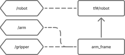
Pinhole projections pinhole-projections
In Rerun, pinhole cameras are not merely another archetype that can be visualized, they are also treated as spatial relationships that define projections from 3D spaces to 2D subspaces. This unified approach allows the Viewer to handle both traditional 3D-to-3D transforms and 3D-to-2D projections.
The Pinhole archetype defines this projection relationship through its intrinsic matrix (image_from_camera) and resolution.
Both implicit & named coordinate frames are supported, exactly as on Transform3D.
With the right setup, pinholes allow a bunch of powerful visualizations:
- the pinhole glyph itself in 3D views
- 2D in 3D: all 2D content that is part of the pinhole's transform subtree
- 3D in 2D: if the pinhole is at the origin of the view, 3D objects can be projected through pinhole camera into the view.
If a transform frame relationship has both a pinhole projection & regular transforms (in this context often regarded as the camera extrinsics) the regular transform is applied first.
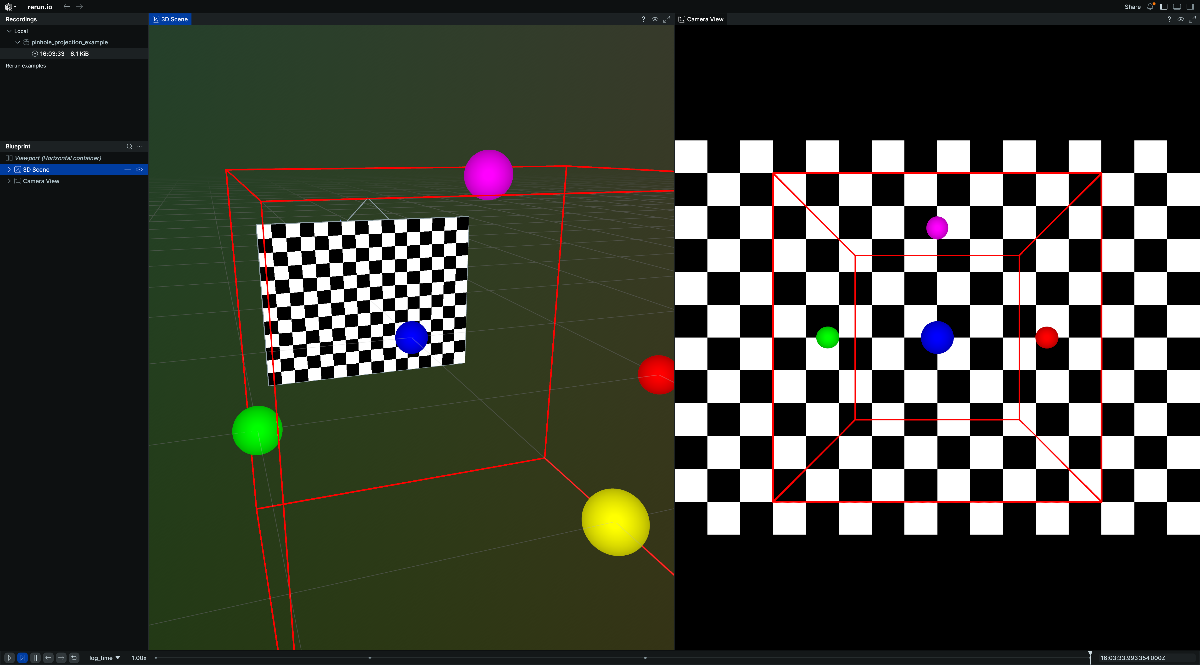
Example: 3D scene with 2D projections example-3d-scene-with-2d-projections
Here's how to set up a 3D scene with pinhole cameras that create 2D projections:
In this example, the 3D objects (box and points) are automatically projected into the 2D camera view, demonstrating how Rerun's transform system handles the spatial relationship between 3D world coordinates and 2D image coordinates through pinhole projections.
"""Demonstrates pinhole camera projections with Rerun blueprints."""

import numpy as np
import rerun as rr
import rerun.blueprint as rrb

rr.init("rerun_example_pinhole_projections", spawn=True)

img_height, img_width = 12, 16

# Create a 3D scene with a camera and an image.
rr.log("world/box", rr.Boxes3D(centers=[0, 0, 0], half_sizes=[1, 1, 1], colors=[255, 0, 0]))
rr.log(
    "world/points",
    rr.Points3D(
        positions=[(1, 0, 0), (-1, 0, 0), (0, 1, 0), (0, -1, 0), (0, 0, 1)],
        colors=[(255, 0, 0), (0, 255, 0), (0, 0, 255), (255, 255, 0), (255, 0, 255)],
        radii=0.1,
    ),
)
rr.log(
    "camera",
    rr.Transform3D(translation=[0, 3, 0]),
    rr.Pinhole(width=img_width, height=img_height, focal_length=10, camera_xyz=rr.ViewCoordinates.LEFT_HAND_Z_UP),
)
# Create a simple test image.
checkerboard = np.zeros((img_height, img_width, 1), dtype=np.uint8)
checkerboard[(np.arange(img_height)[:, None] + np.arange(img_width)) % 2 == 0] = 255
rr.log("camera/image", rr.Image(checkerboard))

# Use a blueprint to show both 3D and 2D views side by side.
blueprint = rrb.Blueprint(
    rrb.Horizontal(
        # 3D view showing the scene and camera
        rrb.Spatial3DView(
            origin="world",
            name="3D Scene",
            contents=["/**"],
            overrides={
                # Adjust visual size of camera frustum in 3D view for better visibility.
                "camera": rr.Pinhole.from_fields(image_plane_distance=1.0)
            },
        ),
        # 2D projection from angled camera
        rrb.Spatial2DView(
            origin="camera",  # Make sure that the origin is at the camera's path.
            name="Camera",
            contents=["/**"],  # Add everything, so 3D objects get projected.
        ),
    )
)

rr.send_blueprint(blueprint)
View coordinates view-coordinates
You can use the ViewCoordinates archetype to set your preferred view coordinate systems, giving semantic meaning to the XYZ axes of the space.
For 3D spaces it can be used to log what the up-axis is in your coordinate system. This will help Rerun set a good default view of your 3D scene, as well as make the virtual eye interactions more natural. In Python this can be done with rr.log("/", rr.ViewCoordinates.RIGHT_HAND_Z_UP, static=True).
Note that in this example the archetype is logged at the root path, this will make it apply to all 3D views. Generally, a 3D view picks up view coordinates at or above its origin entity path.
Pinholes have a view coordinates field integrated as a shortcut.
The default coordinate system for pinhole entities is RDF (X=Right, Y=Down, Z=Forward).
WARNING: unlike in 3D views where rr.ViewCoordinates only impacts how the rendered scene is oriented, applying rr.ViewCoordinates to a pinhole-camera will actually influence the projection transform chain. Under the hood this value inserts a hidden transform that re-orients the axis of projection. Different world-content will be projected into your camera with different orientations depending on how you choose this value. See for instance the open_photogrammetry_format example.
For 2D spaces and other entities, view coordinates currently have currently no effect (#1387).
Pose transforms pose-transforms
InstancePoses3D defines geometric poses relative to an entity's transform frame.
Unlike with Transform3D, poses do not propagate through the transform hierarchy
and can store an arbitrary amount of transforms on the same entity.
For an entity that has both Transform3D
(without child_frame/parent_frame) and InstancePoses3D,
the Transform3D is applied first
(affecting the entity and all its children), then InstancePoses3D
is applied only to that specific entity.
(This is consistent with how entity hierarchy based transforms translate to transform frames.)
Instancing instancing
Rerun's InstancePoses3D archetype is not only used
to model poses relative to an Entity's frame, but also for repeating (known as "instancing") visualizations on the same entity:
most visualizations will show once for each transform on InstancePoses3D
in the respective place.
"""Log a simple 3D mesh with several instance pose transforms which instantiate the mesh several times and will not affect its children (known as mesh instancing)."""

import rerun as rr

rr.init("rerun_example_mesh3d_instancing", spawn=True)
rr.set_time("frame", sequence=0)

rr.log(
    "shape",
    rr.Mesh3D(
        vertex_positions=[[1, 1, 1], [-1, -1, 1], [-1, 1, -1], [1, -1, -1]],
        triangle_indices=[[0, 2, 1], [0, 3, 1], [0, 3, 2], [1, 3, 2]],
        vertex_colors=[[255, 0, 0], [0, 255, 0], [0, 0, 255], [255, 255, 0]],
    ),
)
# This box will not be affected by its parent's instance poses!
rr.log(
    "shape/box",
    rr.Boxes3D(half_sizes=[[5.0, 5.0, 5.0]]),
)

for i in range(100):
    rr.set_time("frame", sequence=i)
    rr.log(
        "shape",
        rr.InstancePoses3D(
            translations=[[2, 0, 0], [0, 2, 0], [0, -2, 0], [-2, 0, 0]],
            rotation_axis_angles=rr.RotationAxisAngle([0, 0, 1], rr.Angle(deg=i * 2)),
        ),
    )
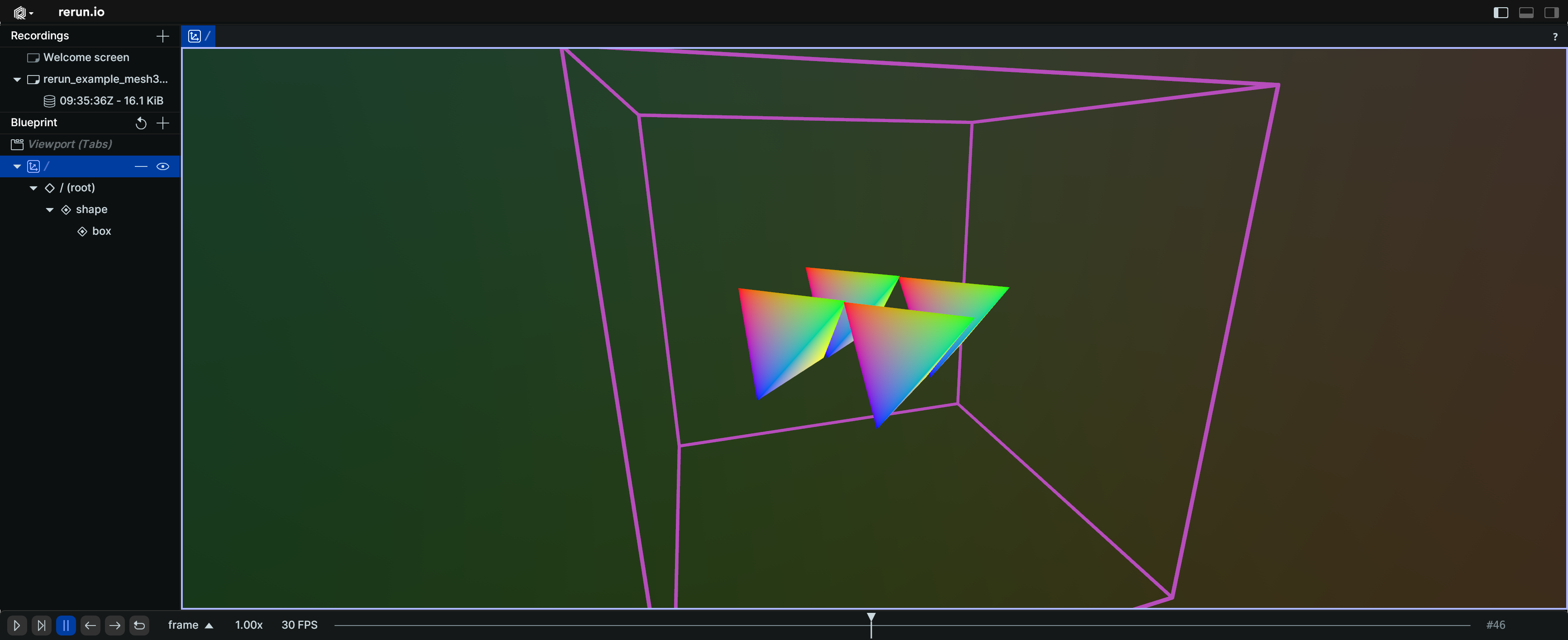
In this example, the mesh at "shape" is instantiated four times with different translations and rotations.
The box at "shape/box" is not affected by its parent's instance poses and appears only once.